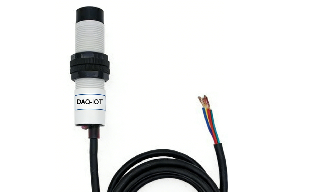
1 Product Overview
The DAQ-GP-CO 2 RS485 uses the industrial standard RS485 bus MODBUS-RTU protocol interface, facilitating connection to various instruments or systems such as PLCs and DCSs for monitoring status quantities like carbon dioxide. Internally, it utilizes a high-precision sensing core and related components, ensuring high reliability and excellent long-term stability. It can be customized with multiple output methods including RS232, RS485, CAN, 4-20mA, DC 0~5V/10V, LoRa, WIFI, 4G , and NB-IoT.
2 Service Philosophy
Our company solemnly promises:
You're not just buying a product, you're also getting meticulous and comprehensive technical support ! ( =^_^= )
This product can be installed on-site by ordinary workers simply by connecting electricity! No debugging is required!
We provide free remote guidance and remote configuration and debugging services, and send data to the cloud platform specified by the user.
We offer free IoT solution consultation services!
3 Technical parameters
Technical parameters | Parameter value | Remark |
CO2 measurement range | 0~5000ppm |
|
CO2 measurement accuracy | ±100ppm |
|
Communication interface | RS485 | A: RS485A; B: RS485B |
Default baud rate | 96008n1 |
|
Power supply | DC6~24V1A | V+: Positive power supply terminal; V-: Negative power supply terminal |
Power supply | DC12~24V1A |
|
Power supply | DC12~24V1A |
|
Operating ambient temperature | -30~85℃ |
|
Operating environment humidity | 5%RH~90%RH |
|
Specifications | Φ14*700*1000 | Diameter, sensor length, wire length |
4 Typical applications

1 Communication Protocol
The product uses the MODBUS-RTU standard protocol format, and all operation or response commands are in hexadecimal data. The default device address is 1, and the default baud rate is 9600,8,n,1.
1. Read data (Function code 0x03)
Query frame (hexadecimal), example of sending: query 1 data from device #1, host computer sends command: 010300000001840A.
address | function code | Starting address | Data length | Verification code |
01 | 03 | 0000 | 0001 | 840A |
For a correct query frame, the device will respond with the data: 010302007979A6, in the following format:
address | function code | length | Data 1 | Verification code |
01 | 03 | 02 | 0079 | 79A6 |
Data Explanation: The data in the command is in hexadecimal. Taking data 1 as an example, 0079 is 121 in decimal. Assuming the data multiplier is 100, the actual value is 121/100 = 1.21. The same applies to other values.
2. Commonly Used Data Address Table
Configuration address | Register address | Register Description | Data types | Value range |
40001 | 0000 | #1 Carbon Dioxide Register | Read-only | 0~65535 |
40101 | 0064 | Model code | Reading/Writing | 0~65535 |
40102 | 0065 | Total number of measuring points | Reading/Writing | 1~20 |
40103 | 0066 | Device address | Reading/Writing | 1~249 |
40104 | 0067 | baud rate | Reading/Writing | 0~6 |
40105 | 0068 | Communication mode | Reading/Writing | 1~4 |
40106 | 0069 | Protocol type | Reading/Writing | 1~10 |
3. Reading and Modifying Device Address
(1) Read or query device address
If the current device address is unknown and there is only one device on the bus, the device address can be queried using the command FA0300660001719E.
Device address | function code | Starting address | Data length | Verification code |
FA, or 250, is the general address. When the address is unknown, address 250 can be used to obtain the actual device address. 0066 is the device address register.
For a correct query command, the device will respond. For example, the response data is: 01030200017984, and its format is shown in the table below:
Device address | function code | Starting address | Model code | Verification code |
01 | 03 | 02 | 0001 | 7984 |
In the response data, the first byte 01 indicates the actual address of the current device.
(2) Change device address
For example, if the current device address is 1 and we want to change it to 02, the command would be: 010600660002E814.
Device address | function code | Register address | Target address | Verification code |
01 | 06 | 0066 | 0002 | E814 |
After the change is successful, the device will return the information: 020600660002E827, the format of which is shown in the table below:
Device address | function code | Register address | Target address | Verification code |
02 | 06 | 0066 | 0002 | E827 |
In the response data, after successful modification, the first byte is the new device address. Generally, the device address change takes effect immediately. At this time, the user needs to make corresponding changes to the query commands of their software.
4. Reading and Modifying Baud Rate
(1) Read the baud rate
The device's default factory baud rate is 9600. If you need to change it, you can do so according to the table below and the corresponding communication protocol. For example, to read the current device's baud rate ID, the command is: 01030067000135D5, and its format is explained below.
Device address | function code | Starting address | Data length | Verification code |
01 | 03 | 0067 | 0001 | 35D5 |
Read the current device's baud rate encoding. Baud rate encoding: 1 is 2400 ; 2 is 4800 ; 3 is 9600 ; 4 is 19200 ; 5 is 38400 ; 6 is 115200.
For a correct query command, the device will respond, for example, the response data is: 0103020003F845, and its format is shown in the table below:
Device address | function code | Data length | Baud rate encoding | Verification code |
01 | 03 | 02 | 0003 | F845 |
According to the baud rate encoding, 03 is 9600, which means the current device's baud rate is 9600.
(2) Change the baud rate
For example, to change the baud rate from 9600 to 38400, that is, to change the code from 3 to 5, the command would be: 010600670005F816.
Device address | function code | Register address | Target baud rate | Verification code |
01 | 06 | 0067 | 0005 | F816 |
Change the baud rate from 9600 to 38400, which is equivalent to changing the code from 3 to 5. The new baud rate will take effect immediately, at which point the device will become unresponsive. To check the device's baud rate, you will need to make the corresponding changes.
5. Reading and Modifying Correction Values
(1) Read the correction value
When data deviates from the reference standard, we can reduce the display error by adjusting the "correction value". The correction difference can be modified within a range of ±1000, that is, the value range is 0-1000 or 64535-65535. For example, when the displayed value is 100 smaller, we correct it by increasing it by 100, the command is: 0103006B0001F5D6. In the command, 100 is hexadecimal 0x64 ; if you need to decrease it, you can set a negative value, such as -100, which corresponds to the hexadecimal value FF9C. The calculation method is 100-65535=65435, which is 0xFF9C in hexadecimal. The device correction value starts from 006B. We will use the first parameter as an example for explanation.
When there are multiple parameters, the method for reading and modifying the correction value is the same.
Device address | function code | Starting address | Data length | Verification code |
01 | 03 | 006B | 0001 | F5D6 |
For a correct query command, the device will respond, for example, the response data is: 0103020064B9AF, and its format is shown in the table below:
Device address | function code | Data length | Correction value | Verification code |
01 | 03 | 02 | 0064 | B9AF |
In the response data, the first byte 01 indicates the current device's actual address, and 006B is the first status value correction register. If the device has multiple parameters, the operation method for other parameters is the same. Generally, temperature and humidity have this parameter, while light intensity usually does not.
(2) Change the correction value
For example, if the current state value is too small, we want to add 1 to its true value. The correction command to add 100 to the current value is: 0106006B0064F9FD.
Device address | function code | Register address | Target address | Verification code |
Device address | function code | Register address | Target address | Verification code |
01 | 06 | 006B | 0064 | F9FD |
After successful operation, the device will return the information: 0106006B0064F9FD. The parameters will take effect immediately after successful modification.
❓ RS485 Infrared CO₂ Sensor – FAQ (Building & Factory Applications)
1. What is an RS485 CO₂ sensor used for in buildings and factories?
It is used to monitor indoor carbon dioxide levels in real time, helping optimize ventilation, improve air quality, and support energy-efficient HVAC control in buildings and industrial environments.
2. How does the infrared (NDIR) CO₂ sensing technology work?
The sensor uses Non-Dispersive Infrared (NDIR) technology to measure CO₂ concentration by detecting how infrared light is absorbed by CO₂ molecules, ensuring stable and accurate long-term performance.
3. Can this CO₂ sensor be integrated with HVAC systems?
Yes. It can be easily integrated with HVAC systems, ventilation controllers, and building automation systems (BAS) using RS485 Modbus RTU communication.
4. What is the benefit of RS485 Modbus communication?
RS485 Modbus allows stable long-distance data transmission and easy integration with PLCs, SCADA systems, and IoT platforms for centralized air quality monitoring.
5. Where is this CO₂ sensor commonly used?
It is widely used in office buildings, factories, schools, hospitals, shopping malls, greenhouses, and industrial ventilation systems.
6. Does the sensor support real-time monitoring?
Yes. It provides continuous real-time CO₂ data output, allowing automatic ventilation control and air quality optimization.
7. Is the sensor suitable for industrial environments?
Yes. It is designed with strong anti-interference capability and stable performance, making it suitable for factories and harsh industrial environments.
8. Can it help reduce energy consumption?
Yes. By monitoring CO₂ levels, the system can adjust ventilation automatically, reducing unnecessary HVAC operation and improving energy efficiency.
 ch
 English